UPDATE:
So before getting into the body assembly and wiring, I have one quick update on some of the previous work I've already done.I've managed to work out some of the code for the Trinket board and I can now have both lasers and proton torpedoes firing. So I've drilled out some holes in the lower half of the nose cone for torpedo lighting.


I am then using more of the same red SMD LEDs that I used for the lasers in the top half and attaching them in front of the holes for the torpedo bays.

Then wiring the up and gluing them into position using Elmer's glue to hold them in place.

As with the upper nose cone, I then cut some shrink tube in half to cover the LED and hole as a light blocker and to confine the light to the hole.


So now it's time to move on to the body portion of the ship.

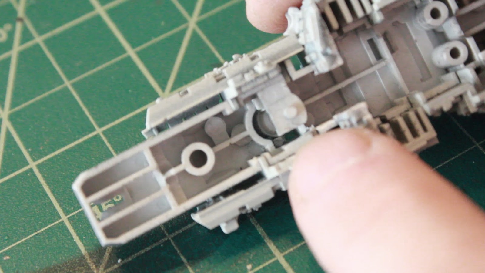
So the first thing I'm doing with the body of the ship is cutting out some trench areas inside the body where I will need to run my wires for all of my lighting.


Now that I've got my areas routed out for wiring it's time to remove the rest of the body pieces, then prime and a coat of black...

Then paint with the body color of Tamiya AS-20.

Now the instructions have you put the bottom and top half of the body together first and then attach the sides, but because of the way I'm building this kit with all of my lighting, I'm doing it in a slightly different order, and in a way where I can easily access the insides again if need be due to any LED outages. So it's time for me to attach the side pieces.


With the sides now attached, I need to work on how I will be mounting the model and running all of my wires. I will be using a 3/16" piece of copper tubing. I want my model angled slightly upward and tipped to the left. So I'm going to drill a hole through the bottom portion of the body at an angle in the same position that the kit stand would attach to.

Here, the hole is drilled out and has the copper tubing temporarily attached. You can see the slight pitch of the body on the tubing and also see through where my wires will run.


I also need to cut out an area of the upper body to make room for my breadboard that I will be using to power my LEDs.


The other issue I need to deal with is my R2 unit.


I also cut out an area in the body where R2 sits so that wires can run through.

But R2's leg is in the way, as can be seen here.

So because my R2 unit will not be removed from the model and you'll never see below his head really, I'm going to cut his legs so that there's room for my wires inside the body of the ship.


You can see here now how with the R2 unit in place, there is an area for my wires.
So now that the upper body half is prepped and ready, I can now attach the upper body half into the upper nose cone half...

And then run my wires from the nose cone sections through my routed opening into the body.


I then soldered a power connector to my little breadboard I've cut out to go in the body. I've run a strip of wire down either side for the positive and negative wires of the LEDs to attach to.


So I then soldered my nosecone positive and negative LEDs to the appropriate areas of my breadboard. The 2 remaining wires (yellow and red in upper part of photo) are the laser and torpedo trigger wires. These will be soldered to a corresponding wire on my 3 wire connector I'm attaching to the breadboard.

I've cut some styrene tube into small pieces as stand offs for my breadboard to attach to in the body.

I then glued them in place in the upper body...

And then glued my breadboard down in place.

My engines are then slid into position in the body and again, the positive and negative wires soldered to the appropriate area of my breadboard. The 2 remaining black wires of my engines are the trigger wires which will be attached to the 3rd leg of my 3 wire connector.


I've done a quick test plugging in my power and trigger connectors to my Trinket control board and everything is working just as I had planned it. Though I will not be showing that at this time.
So before I can finally close her up, I need to deal with my R2 unit. I'm wanting to light it up as well. So I purchased some very small SMD LEDs that are color changing, to use for the R2 units main circular eye. And I mean VERY small.


I then soldered positive and negative wires to either end of the SMD, which surprisingly I did very easily. I thought it would be much more difficult, but using the right equipment makes it pretty easy.


And then a test of the LED to make sure it works ok after my wire attachment.
So with having my lighten worked out, first I'm going to paint my R2 unit black, which is the color of Gold Leaders R2 in the movie.


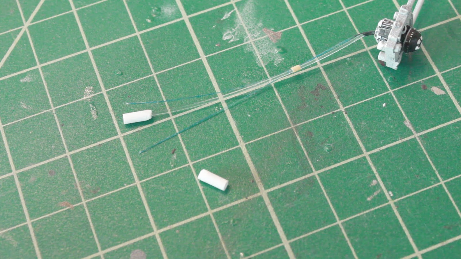
Next is drilling out the holes for the fiber optics to light my R2 unit. One large hole for the main eye and color changing light and 2 small .25mm holes for white light.


Then it's time to do the detail painting. Now I will only be painting the head and down to the top of the shoulders. Everything else is buried inside the Y-Wing, and because my R2 unit will be wired with working lights, he will not be removable. So no need to paint the whole body.


Now that the R2 unit has been painted, I need to drill out the center of the body so that my fibers can run through to light up his eyes.


Now that I have the path drilled out for the fibers, I run the .75mm fiber into R2's main eye and two .25mm fibers in each of the little eyes on the front and back. I also painted the tip of the .75mm fiber with black, so when there's no light, it appears black. But when light shines, it shows through the black.


I then filled in the head with Elmer's glue to hold the fibers in place so they don't slip out, and I wrapped a bit of tape around the fibers holding them together.

I then painted the inside of the head and a portion of the fibers black to block any light leakage.

The R2 unit's main eye really only does red and blue. As my RGB LED is red, green and blue, I'd prefer that it just did red and blue. So I examined the LED closely to figure out which portion did the green, and under extreme magnification, found this is where the green LED is.

So I decided to very carefully take an exacto blade are slowly cut and poke through the plastic housing of the LED to get down to the wire that supplies the green LED with power. Hopefully severing that wire, thus eliminating the green LED from the sequence of color change.

After going through about 5 of these LEDs (luckily about .25 each), I finally got one to work with just red and blue.
At this point, I took a small piece of shrink tube and heated it with my heat gun to shrink it down around the LED, creating a tube for my fiber optic to go into the get it's light.

I then did the same for a white SMD LED for the other 2 eyes (or projectors) on the R2 unit. I also soldered in a resistor on each LED to protect from too much voltage.

I then placed the 2 LEDs inside the body of the Y-wing, securing them in place in the rear of the body, to where I would run the fibers of my R2 unit.

I then glued a small piece of styrene tube to the end of the .75mm fiber to fit inside the RGB LED tube that I had just made.
It was then time to install the R2 unit into the upper body...

I then ran the .75mm fiber and .25mm fibers into the corresponding LEDs in the bode of the Y-wing.


After a quick test of the R2 unit and all other lighting once again, it's finally time to attach my plugs to the breadboard I made, run the wires out through the bottom half of the body and secure in place.


And one more quick test of all of my lighting, and everything works as planned. While I'm not going to show everything working at this point, I will show how the R2 unit looks.


So there we have it. The entire Y-wing pretty much assembled. It will then be time to attach all of the piping to the body and then do the weathering and detail painting, as well as attach and wire up all of the electronics in the base of the model to power and run everything.
Stay tuned. Much more to come...
No comments:
Post a Comment